|
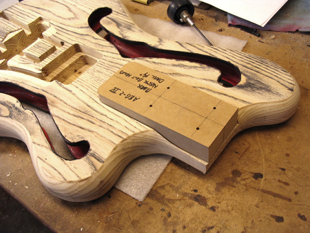
Now for the final details! This template fits into the neck pocket and a transfer punch is used to mark the locations of the neck bolt holes.
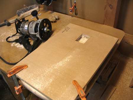
The body is flipped over and this routing fixture is used to cut the recess for the neck plate. That small plug behind the router fits into the holes that were just drilled, and is used to align the routing fixture before clamping.
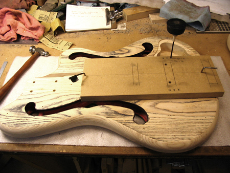
This template plugs into the reference holes and is used to transfer punch the hole locations for the bridge cover anchors.
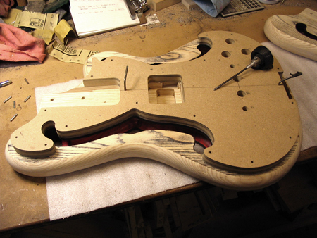
The master template for the pickguard is plugged into the reference holes and is used to transfer punch the hole locations for all of the pickguard screws. This is the same template that is used to make the pickguard, as covered in the Hardware section.
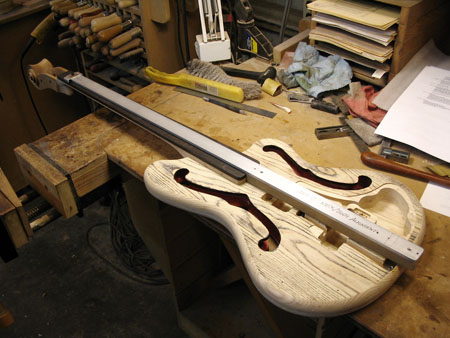
Finally, the neck is fitted to the body. It's attached with the neck bolts, and the alignment is checked with this long bar gauge, which also plugs into the reference holes in the body. While held in alignment, the holes for the two dowel pins are drilled in from the back of the body into the neck heel.
|
|
|
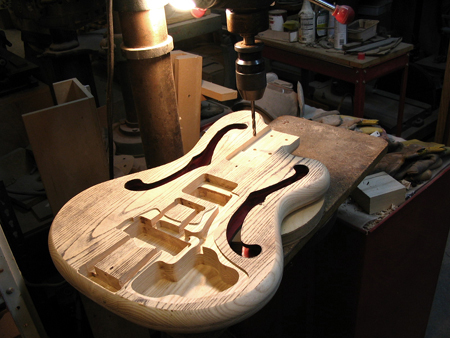
The holes for the neck bolts are drilled through from the inside of the neck pocket.
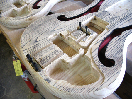
The aluminum anchor blocks for the P-pickup frame are set into their cavities in epoxy. Cap screws are waxed and threaded into the tapped holes in the blocks to keep the epoxy out of the threads.
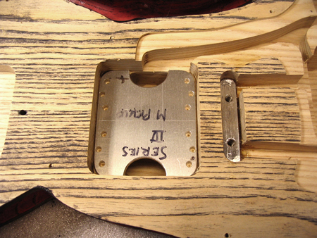
This template fits into the M-pickup cavity and is used to transfer punch the hole locations for the mounting screws and adjustment screws.
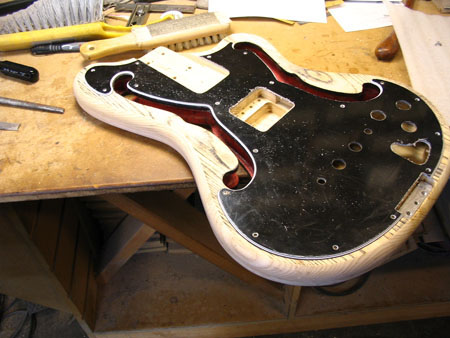
The partially-completed pickguard is temporarily screwed on to the body and checked for fit. The edges around the inside of the F-holes are gently trimmed flush with files.
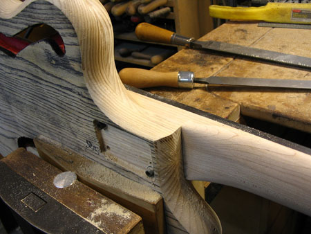
The cutaway area is filed smooth and flush with the side of the neck. The body is ready for the paint process!
|
Back To Start Of Building Bodies..
|

