| Home || Site Map || About This Company || Meet The Staff || Shop Tour | Other Services Available:| Custom Necks || Ampeg Restorations & Parts || Metalworking For Electronics |
New Instruments:| AEB-2 & AUB-2 Scroll Basses || The New Devil Bass || SSB Short Scale Bass || Prices & Options || Current Order Log || Cases || Strings |
Building Scroll Basses:| Overview || Necks || Bodies || Paint || Pickups || Hardware || SSB Technical |
Vintage Ampegs: | Overview || AEB-1 & AUB-1 || ASB-1 & AUSB-1 || AMB-1 & AMUB-1 || SSB & SSUB || Technical Info |
Other Things That You May Find Interesting:| Clients & Projects || Custom Necks Gallery || My Antique Machinery || The Bass Banjo |


Building Scroll Basses
The Pickups...Page 6

Back To Previous Page..
Back to start of Pickups


With the pickup assemblies completed, the control circuit is mechanically assembled and wired up. The entire assembly is installed into the body. I deliberately designed the body and hardware so that the entire pickup system can be installed and removed without having to unsolder any wires. The wire bundles lay in routed troughs in the body, and are covered by aluminum plates. The control cavity, pickup cavities, and wire troughs are all shielded with a spray-on nickel paint called Super Shield (shown in the Building Bodies section). The aluminum plates complete the shielding enclosure. The plate over the control cavity also provides a solid mechanical mounting for the input jacks and pots.

The control system is a simple passive circuit. I use the highest quality components that I can find to make it reliable for many years. The pots are sealed mil-spec units with stainless housings, stainless shafts, and bronze bushings. They're made for military radio systems. I've never yet had one fail or get dirty. The input jacks are Switchcraft parts. The capacitors are high grade polyester. The wire is all 22ga stranded, kept short and soldered carefully.


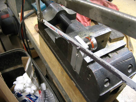
The shafts of the pots have to be shortened about 1/4". This simple holding fixture fits in a vise and clamps the shaft while I saw it off with a hacksaw.
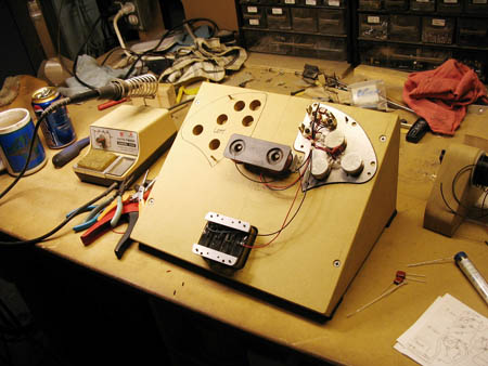


This is the wiring fixture that I made up. It holds the pickups and control plate upside down in the correct relation to each other, so I can make the harnesses fit neatly. It'll hold either left hand or right hand harnesses. I built it up at that angle to reduce neck strain!
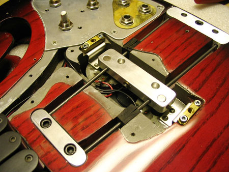


The P-pickup frame, including the magnets and rubber damping blocks, is installed in its recesses over the P-pickup coil assembly. Three machine screws hold it tightly down to the aluminum anchor blocks embedded in the body. The tailpiece also fastens down to the rear anchor block, through the rear block of the P-pickup frame. Mechanical rigidity is really important here. The frame is checked for movement and clearance. A ground wire from the control plate connects to the center block of the frame to ground the strings through the bridge.


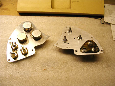
Here are the pots and jacks assembled to the control plate. The thin triangular brass plate around the input jacks is just for looks; it shows through the opening in the pickguard.
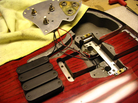


Installing it in the body: The M-pickup and P-pickup assemblies are set down into their pockets and fastened down with socket head machine screws. The P-pickup mounting bracket is held down by the two brass blocks which also provide the threads for the bridge cover screws.
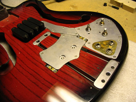


Finally, the system is closed up by screwing down the control plate and two cover plates. It's all tested through a bench amp before going any further.


Back to start of Pickups